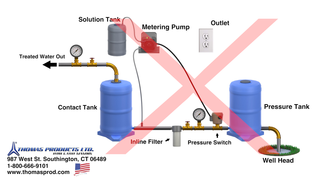
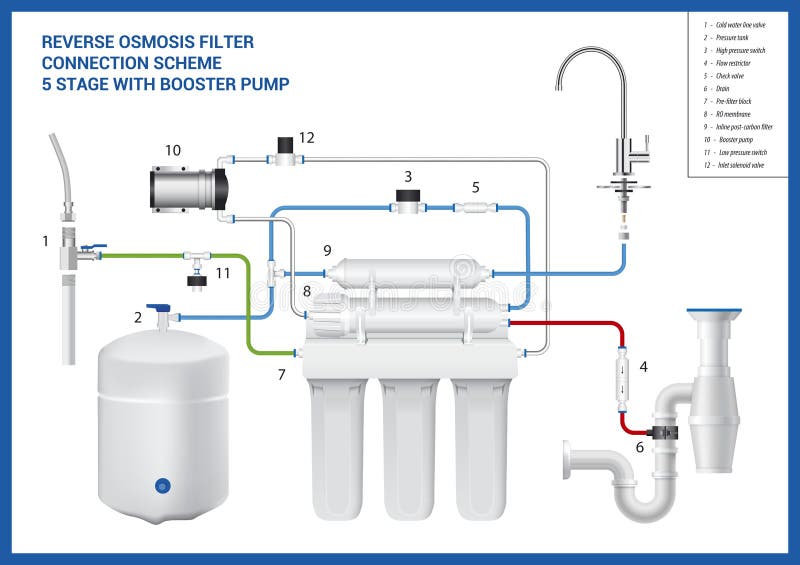
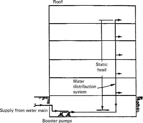
5+ booster pump installation diagram
Plumb the dedicated line upstream of all air inducing equipment. Available Plug N Play.
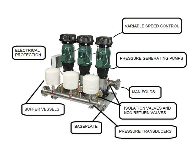
Pump Controls Product Overview Pump Control Design Thomas Products Ltd
Pump Intake Connect to vacuum switch To brake booster 5 Next wire the fuse to a positive ignition switched power source.
. Proven on our own Hellcat and Demon test cars and Fuel Flow Bench. Diagram 5 Stage RO with UV Booster Pump and Permeate Pump By h2osplashwaterfilters Diagram of a 5 stage Reverse Osmosis system with UV light Booster. Refer to the Typical Installation diagram and adhere to the following guidelines for specific equipment.
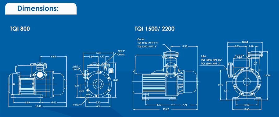
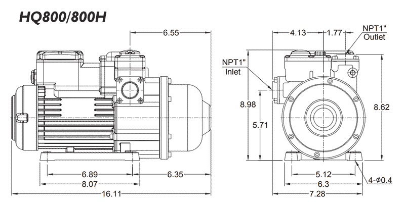
The Prodigy Series is a highly compact customizable package designed for HIGH FLOW LOW BOOST applications. System Components Booster Pump Reverse Osmosis Systems need sufficient pressure to operate correctly 50 - 65 psi is ideal. Pump is exceptionally quiet and uses up to 40 less electricity than competitive booster pumps.
-To disassemble the booster pump - 1. All controls are protected within a NEMA 3R forced-air ventilated enclosure with inlet filter and NEMA 4X active incoming surge suppressor with LED indicator. If a heater is.
BOOST-RITE Universal Booster Pump Installation and Users Guide iv For Installation of Electrical Controls at Equipment Pad ONOFF Switches Timers and Automation Load Center. Unscrew suction line in middle of volute. Pump design allows for easy installation and service.
Check my resent upload videohttpsyoutubeEqNenMs_Wrk booster pump repairbooster pump and pressure tankbooster pump installationbooster pump for wash. The location should be away from direct sunlight and excessive. Plumb the dedicated line upstream of all air inducing equipment.
Refer to the Typical Installationdiagram and adhere to the following guidelines for specific equipment. End suction pumps with 304 stainless steel casing and impeller. Turn off booster pump motor and close valves.
A Positive connection must be a switched. Suitable for use with all pressure. Loosen nuts and remove bolts between booster pump volute.
Utility Knife Step 1 Mount the Controller Box Find a suitable location for the controller box to be mounted. Regulates pump voltage so fuel flow is not affected by electrical loads and voltage variations. If your water pressure is low you can add a Low Pressure.
It features NSF 61 Rated 304 SS.

Dik Geurts Dg Ivar 5 Wood Burning Stove 5kw Multifuel Via Kit Stovefitter S Warehouse

Auto Ms Booster Pump 2 2kw Water Booster Pumps Sa
Water Booster Pumps Fresh Water Systems
Booster Pumps For Boosting Water Pressure
Reverse Connection Stock Illustrations 575 Reverse Connection Stock Illustrations Vectors Clipart Dreamstime

Calameo Booster Pumps Wiring Diagram
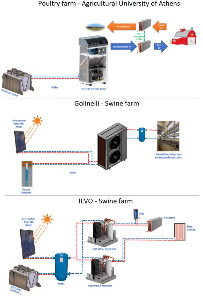
Adaptation Of Innovative Technologies For Livestock Farming Res4live

Pressure Pump Installation User Guide Youtube
How Much Could A Booster Pump Energy Check Save You

Compact Davey Booster Pumps For Homes Primo Supply
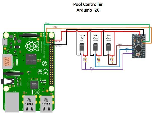
Pool Controller Arduino Project Hub

Booster Pump Installation Instructions Pdf
Booster Pump Article About Booster Pump By The Free Dictionary

Pressure Pump Fitting User Guide How To Pressure Pump Installation Youtube

Pressure Pump Installation User Guide With Full Details Youtube

Optical Pressure Sensor Based On The Emission And Excitation Band Width Fwhm And Luminescence Shift Of Ce3 Doped Fluorapatite High Pressure Sensing Acs Applied Materials Interfaces

Water Pressure Booster Pump Installation 10 Step Guide Home Inspector Secrets